LIF Frequency Conversion
Some LIF setups don’t shine the tunable laser directly on the sample: its output passes through one or more optical stages — a doubling crystal, a mixing crystal — before the beam reaches the sample. The Conversion tab lets you describe that optical path, the frequency-conversion chain, so Blackchirp can show the actual excitation wavelength or frequency reaching the sample (not just the laser’s own tuning value) and automatically drive any motorized conversion stages to track the laser as it scans.
If your LIF setup shines the tunable laser directly on the sample with no intervening optics, the tab’s table is empty and there is nothing to configure here — the excitation beam is simply the laser output. Most users with a bare tunable laser can skip this page.
The Conversion tab sits alongside the Acquisition tab (covered on the LIF Configuration page) on the LIF Configuration page of the Experiment Setup wizard, and is visible whenever the LIF module is enabled (see Application Configuration).

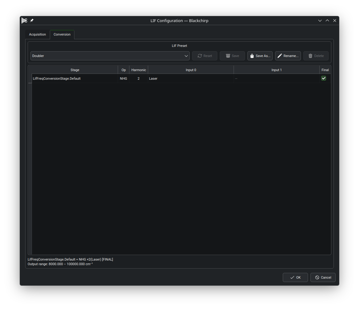
The Conversion tab: one row per conversion stage with its operation, harmonic order, input wiring, and FINAL marker, and the resolved excitation-beam preview below the table.
The Stage Table
One row appears for every conversion stage — a LIF Conversion Stage device — present in the active hardware loadout. Rows are not added or removed from this page; if you need another stage, add its driver profile through the hardware configuration and it appears here automatically. Each row’s columns are:
- Stage
The stage’s hardware key, fixed by the hardware loadout.
- Op
The stage’s conversion operation — NHG, SFG, or DFG (see Conversion Operations below). This is set by the stage’s hardware profile and cannot be changed from the table.
- Harmonic
The harmonic order for an NHG stage. The cell is read-only; change it with the Change harmonic… context-menu action described in Changing the Harmonic Order. The value has no effect for SFG/DFG stages.
- Input 0 / Input 1
The stage’s primary and secondary input beams — see Choosing Inputs below. Input 1 only applies to SFG/DFG stages; for an NHG stage the cell is disabled and shows “—“.
- Final
A checkbox marking this stage’s output as the excitation beam — the beam that reaches the sample. Checking one row’s Final box unchecks every other row; exactly one stage must be marked before the chain is usable. See Live Preview below.
Conversion Operations
Each stage performs one of three operations, shown literally in the Op column:
- NHG
N-th harmonic generation (doubling, tripling, …): the stage’s output is its single input multiplied by the Harmonic order.
- SFG
Sum-frequency mixing: the stage’s output is the sum of its two inputs.
- DFG
Difference-frequency mixing: the stage’s output is the difference of its two inputs.
Choosing Inputs
Click an Input 0 or Input 1 cell to choose that beam’s source from a drop-down:
- Laser
The tunable laser’s own output — the laser’s tuning value, with no conversion applied.
- Another stage’s hardware key
The output beam of another stage already in the table, letting you chain stages together (for example, mixing a doubler’s output with the laser fundamental in a downstream SFG stage).
- Fixed…
A constant, non-scanned mixing beam. Choosing this option prompts for the fixed mixing-beam wavenumber (cm⁻¹), which is then used for every point of the scan.
Live Preview
A panel at the bottom of the tab renders the assembled chain as it is currently configured. With no conversion stages, it reads:
Laser → FINAL (identity, no conversion stages)
With stages configured, each row is summarized in the form
stageKey = Op(inputs), with [FINAL] appended to the stage
marked as the excitation beam. For an NHG stage the operation label
carries its harmonic order, rendering as NHG ×N (for example,
NHG ×2 for a doubler); SFG and DFG stages show the bare SFG or
DFG label. Below the chain expression, when the
chain fits together, Blackchirp reports the excitation-beam range that
corresponds to the laser’s full tuning range, for example:
Output range: 14000.000 – 15000.000 cm⁻¹
If a loaded configuration or preset refers to a stage that is no longer part of the active hardware loadout, the preview lists it separately as a dropped stage so you know it was silently excluded from the assembled chain.
Changing the Harmonic Order
The Harmonic column is read-only; to change it, right-click the stage’s row and choose Change harmonic…. The action is only enabled for NHG stages — for SFG/DFG stages it is grayed out, since harmonic order does not apply to them. Choosing it prompts for a new integer harmonic order (1–20); the change is sent to the stage’s hardware, and the Harmonic column updates only once the hardware confirms the change succeeded.
Troubleshooting
If the chain doesn’t fit together, the live preview replaces the output range with a validation error describing the problem. Common causes:
Wrong number of inputs for the operation. An NHG stage needs exactly one input; SFG and DFG stages need exactly two. Fill in the missing Input 0 or Input 1 cell.
No stage — or more than one stage — marked as the excitation beam. Check exactly one row’s Final box.
A cycle in the chain. One stage’s input traces back to its own output through a chain of other stages; re-check the Input 0 / Input 1 selections that form the loop.
The excitation beam doesn’t depend on the laser at all. Every chain must trace back to Laser somewhere along the path to the excitation beam; a chain built entirely from Fixed… inputs, or one where the laser’s contribution cancels out (for example, a DFG of two equal multiples of the laser), is rejected because there would be nothing to scan.
See also
LIF Presets — saving and restoring named conversion-chain configurations
LIF Conversion Stage — the conversion-stage hardware type and its drivers
LIF Data Storage — the on-disk liftopology.csv
record of the chain used by a given experiment