Acquisition Types
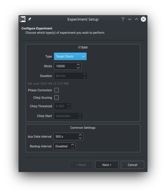
When starting a new experiment, the first page of the wizard allows for selecting the desired type of the FTMW acquisition, as well as other options related to real-time FID processing. The type of the acquisition determines how many FIDs will be recorded, and in some cases, how the entire spectrum will be partitioned into multiple segments. Available acquisition types are:
Real-time processing includes phase correction (adjusting for slow temporal phase drift during long averages) and/or chirp scoring, which attempts to reject “weak” chirps.
Target Shots
Target Shots is the default and most straightforward type of acquisition.
In this mode, FIDs are recorded and averaged until the desired number of shots (as indicated in the Shots box) is reached.
This is considered a single segment acquisition: only a single Rf/Clock configuration is used during the experiment.
In this mode, the Duration box is disabled and the Backup Interval box is enabled.
Target Duration
Target Duration mode records and averages FIDs until a period of time has elapsed.
The desired acquisition duration is specified in the Duration box, and an estimate of the experiment completion time is provided in the text below the box.
Note
The estimated completion time is computed simply by adding the duration to the current time, and does not account for the time spent configuring the remainder of the experiment and initializing. The actual experiment timer begins after the experiment has been successfully initialized.
This mode is also a single segment acquisition.
The Shots box is disabled and the Backup Interval box is enabled.
Forever
In Forever mode, FIDs are recorded and averaged until the user hits the abort button or a critical hardware failure occurs.
Accordingly, the Shots and Duration boxes are disabled when this mode is selected.
Like Target Shots and Target Duration, this is a single segment acquisition, and therefore the Backup Interval box is enabled.
Note
Blackchirp supports averaging up to \(2^{64} - 1 = 18446744073709551615\) shots. However, each FID data point is stored as the sum of raw digitizer counts and therefore overflow of an FID data point may occur before this limit is reached. See FID CSV Files for more details.
Peak Up
Peak Up mode acquires and averages FIDs until a target number of shots is reached, but does not stop at that point. Processing continues as a modified moving average, which is a special case of an exponetially-weighted moving average. The average can be reset and the number of shots included in the average can be changed during the acquistition with the controls on the CP-FTMW Tab.
Warning
Unlike the other acquisition modes, Peak Up mode experiments are not saved to disk. Once a new experiment has been started, the results from the Peak Up mode experiment are discarded. Be sure to export any data you wigh to save manually!
Another key difference between Peak Up mode and the other acquisition modes is that most program controls (hardware, settings, etc) remain unlocked and can be modified without stopping the acquisition. For example, gas flow rates or pulse timings may be modified and the results monitored in real time.
Warning
In certain situations (e.g., when a delay generator produces a protection pulse for a switch), it may be possible for the user to enter settings that are inappropriate. Use caution when changing settings during a Peak Up mode acquistiion.
Note
Under the hood, Blackchirp applies an 8-bit left shift to all digitizer values during peak-up mode, equivalent to multiplying each ADC value by 256. This creates extra bits that are needed for the rolling average operation.
LO Scan
The LO Scan mode implements a version of segmented CP-FTMW spectroscopy in which a certain number of FIDs are acquired and averaged, then the upconversion and/or downconversion local oscillators are stepped.
By sampling a variety of LO frequencies, the spectral range covered by the instrument can far exceed the instantaneous bandwidth of the FTMW digitizer, allowing CP-FTMW spectroscopy to be performed with (comparatively) inexpensive hardware.
On the CP-FTMW Tab, each frequency segment can be viewed individually, and algorithms are available for stitching together the entire spectrum and deconvolving dual sidebands (see the linked page for more details about these algorithms).
As a multi-segment acquisition type, Blackchirp writes a backup each time the segment changes, and therefore the Backup Interval box is disabled.
The Duration box is also disabled.
The Shots box is enabled, and the value entered in this box is used as the default value for the number of shots per LO step (though it can be changed on a later step).
Note
After selecting LO Scan, the Rf Configuration box will be shown on the next screen. In order to proceed, both an UpLO and a DownLO clock source must be set (or, if the Common LO box is checked, then only the UpLO needs to be set). The exact frequencies entered for these clocks are unimportant, as they will be configured on the next page.
During an LO Scan, Blackchirp will acquire the indicated number of Shots/Point at each LO frequency specified.
The complete set of LO frequencies is consided one sweep, and Blackchirp will return to the beginning LO configuration and resume integrating until the desired number of Target Sweeps is reached.
When Blackchirp repeats a segment, the new FIDs are automatically averaged together with the ones from the previous sweep(s).
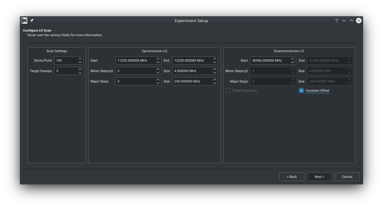
On the right side of the dialog, you can configure the LO frequencies that are covered during the acquistiion.
If the UpLO and DownLO correspond to the same output, then the Downconversion LO box will be disabled.
Blackchirp divides the scan range into major and minor steps.
Essentially, at each major step, a series of measurements can be made with slightly shifted LO positions to assist with sideband deconvolution.
The LO is incremented by the minor step size for each minor step associated with the indicated major step.
In the screenshot above, the Upconversion LO covers the total range of 1008 MHz in 5 major steps plus 3 minor steps per major step.
Given the minor step size of 4 MHz, the major steps work out to 11520, 11770, 12020, 12270, and 12520 MHz.
At each of these major step values, 3 minor steps are recorded, separated by 4 MHz: 11520, 11524, 11528, 11770, 11774, 11778, …, 12520, 12524, 12528 MHz, for a total of 15 (3x5) steps.
As the Start, End, and major/minor steps boxes are adjusted, some of the other boxes’ values are updated to ensure the range is consistent.
The Downconversion LO is configured similarly.
As the number of major/minor steps is changed, the downconversion LO steps and step sizes are also adjusted to ensure the number of steps is the same and that the step sizes are consistent with the indicated range.
The two boxes at the bottom modify the behavior.
If the Fixed Frequency box is checked, then the Downconversion LO is not changed during the acquisition; its frequency remains at the start value, and all other boxes are disabled.
If the Constant Offset box is instead checked, then the Downconversion LO frequency at each step will be set to maintain the same difference in frequency between the Downconversion LO start frequency and the Upconversion LO start frequency at each step.
For example, in the screenshot above, the Downconversion LO is offset from the Upconversion LO by \(40960-11520 = 29440\) MHz.
This difference will be kept constant as the Upconversion LO is stepped through its indicated values.
DR Scan
In a DR Scan (double resonance), FIDs are recorded while a second DR Clock source is scanned across a desired frequency range in a series of steps.
The purpose of this scan mode is to monitor the intensity of one or more transitions as a function of the DR Clock frequency: when two transitions share a common state, the intensity of a line may be depleted or enhanced, depending on the pulse powers and timings.
Like the LO Scan mode, this is a multi-segment acquisition mode.
The Duration and Backup Interval boxes are disabled, and the value entered in the Shots box will be used as the default number of shots per point when the DR scan parameters are initialized.
Note
After selecting DR Scan mode, on the Rf Configuration page it will be required that a physical clock sourse is assigned to the DR Clock role.
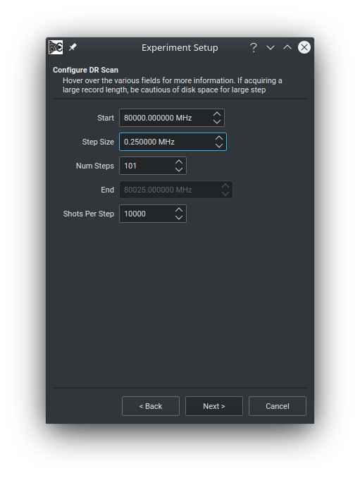
To set up a DR scan, enter the desired starting frequency, step size, number of steps, and shots per point.
The End box will be updated to show the final DR frequency automatically.
When viewing the DR Scan on the CP-FTMW Tab, there is currently no ability to view a peak intensity directly as a function of the DR frequency.
Instead, it is recommended to make use of the FT1 - FT2 plot mode, as discussed in more detail on the that page.
Other Experiment Options
In addition to the acquisition type, other options accessible on the first wizard page involve real-time FID processing (phase correction and chirp scoring), auxiliary data, and backups (discussed on the Data Storage page).
Phase Correction
Time-domain averaging requires that FIDs are mutually in phase with one another.
This is typically achieved by locking all oscillators to a common reference frequency generated by a stable source such as a rubidium clock.
However, in some cases, over the course of a long acquisition, some phase drift may occur (we discovered this one winter day at Harvard when a lab door to the outside was open for 30 minutes for moving equipment out, and the intensity of an OCS signal steadily decreased).
To mitigate this potential case, Blackchirp has a “phase correction” algorithm that attempts to correct for slow phase drift.
This algorithm can be enabled by checking the Phase Correction box.
In order to work, the FID record from the digitizer must contain the chirp, and the chirp should not be saturated on the scale of the digitizer. Often the leakage through a switch is sufficient, but we have also used directional couplers and/or SPDT switches with some success to allow an attenuated version of the chirp to bypass a diode limiter/protection switch combination. Blackchirp attempts to determine where the chirp is located within the wavefunction (more on this below), and then computes the cross correlation between the chirp in the new record with the current average chirp after at least 20 FIDs have been recorded. This calculation is performed with trial shifts of up to a few points in time to determine the maximum. Usually the shift is 0, but over time a nonzero shift may accumulate due to, e.g., temperature fluctuations. Blackchirp attempts to be conservative, only changing the current shift if there is a significant improvement in the computed figure of merit. If the size of the shift becomes too large (current limit is 50 points), an error is thrown.
If the Chirp Start box is set to Automatic, Blackchirp assumes that the digitizer is triggered at the start of the protection pulse.
The chirp start is then set to the sum of the pre-chirp protection and pre-chirp delay settings entered on the Chirp Setup page, and the chirp end is determined from the chirp duration entered on that page.
These computed values will be displayed on the FID plots displayed on the CP-FTMW Tab.
If they are not correct, you can override the chirp starting time by entering the actual chirp start you observe into the Chirp Start box.
The duration still comes from the Chirp Setup value.
Chirp Scoring
Occasionally, amplifiers may show significant shot-to-shot jitter in the chirp amplitude.
By enabling the Chirp Scoring feature, Blackchirp will compute the squared sum of the chirp embedded in the FID record (as described above) and compare it to the squared sum of the averaged chirp.
If the new value falls below the fraction of the averaged chirp value indicated in the Chirp Threshold box, the FID is rejected.
Higher values of the threshold result in more strict acceptance criteria.
Similar to the Phase Correction algorithm, the chirp scoring routine requires that the chirp be visible and unsaturated within the digitizer record, and its position may be manually adjusted with the Chirp Start box.
Warning
Setting the chirp threshold too high will result in a large fraction of chirps being rejected, and an acquisition may therefore appear to stall.
Aux Data Interval
Finally, the desired interval for Aux Data readings can be set at the bottom of the wizard’s starting page. More frequent readings will increase data storage requirements, but will also provide more regular opportunities to automatically abort an acquisition using one of the validation conditions.