Digitizer Setup
The Digitizer Setup page contains the settings that will be sent to the FTMW digitizer which records FID data in a CP-FTMW acquisition.
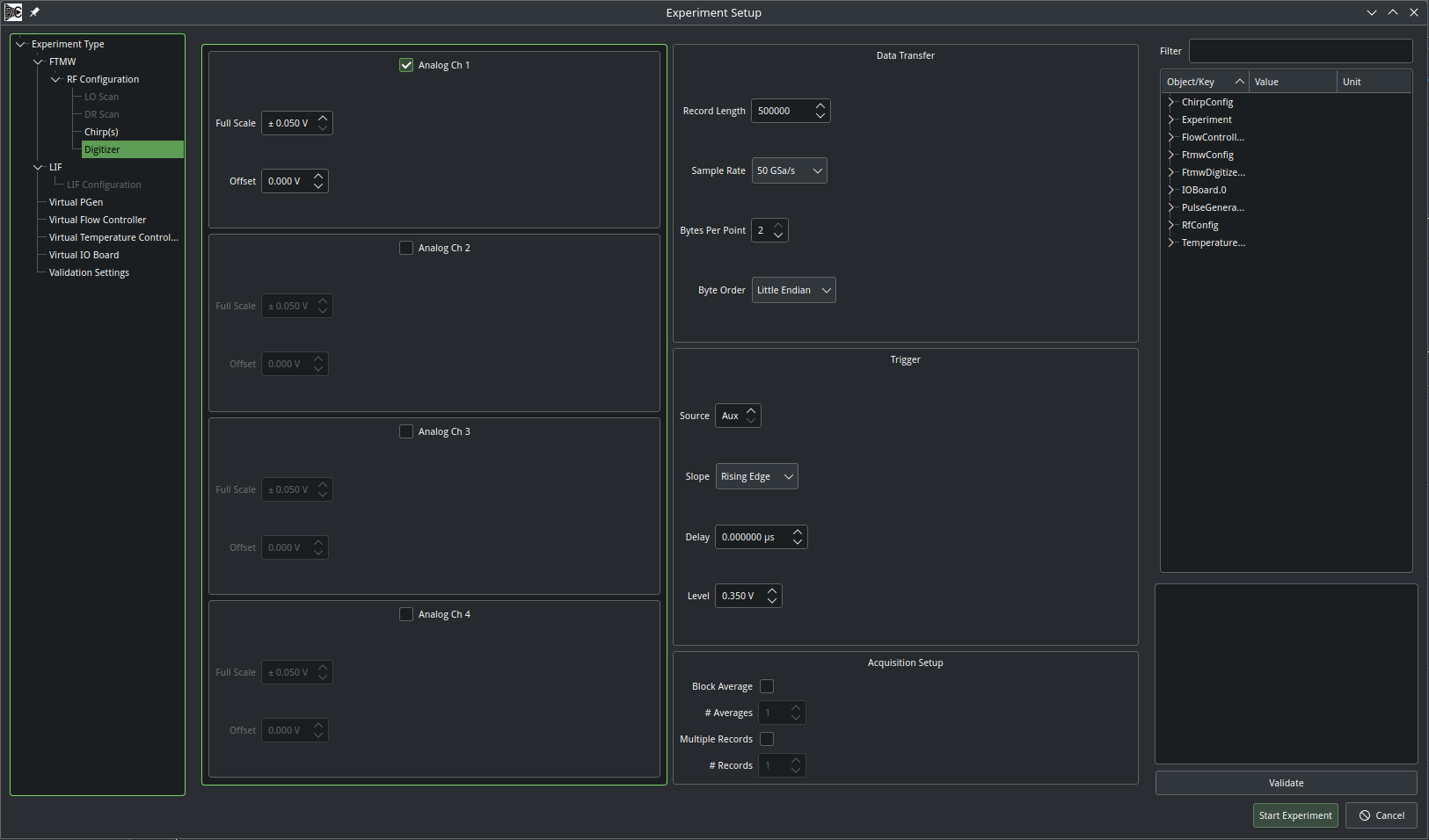
Analog Channels
Each analog channel on the scope is displayed on the left side of the dialog. Use the checkboxes to select which channel contains the FID data. Only one channel may be selected. For that channel, you can configure the full vertical scale (minimum to maximum, not per division) and the offset. If DC coupled, the range of the signal is offset +/- full scale.
Note
In general, the oscilloscope coupling should be set to AC, if supported. The vertical offset should therefore always be 0. However, if there is a need, Blackchirp could add a feature which controls the coupling for each vertical channel.
Data Transfer
These settings control how the waveform is configured and encoded as it is transferred from the digitizer to Blackchirp. The record length is the number of samples in the FID and the sampling rate sets the time interval between samples and the digital bandwidth of the Fourier transform. Dividing the record length by the sample rate yields the total time spanned by the FID waveform, which dictates the resolution of the Fourier transform. Blackchirp should have sensible default sample rates for each FTMW digitizer, but the options can be customized by configuring the settings in the FtmwDigitizer hardware menu (see also the FTMW Digitizer options.
Bytes per point and byte order control the encoding of data sent from the digitizer to Blackchirp. Where possible, Blackchirp requests that data be transferred in binary as the raw digitizer reading. Bytes per point dictates the number of bytes per sample which may be dictated by the raw ADCs (1 byte for 8-bit records, 2 byte for 12 or 16-bit records) or by the bit width of segmented memory for acquisitions that involve on-board averaging prior to data transfer. For multi-byte records, the byte order determines whether the most significant byte comes first (Little Endian) or last (Big Endian). A digitizer implementation may override these settings with more appropriate values as needed.
Trigger
Blackchirp assumes that the digitizer is triggered with an edge signal. The trigger channel, slope, delay, and level can be set here. It is important to ensure that these settings are appropriate for your configurations.
Note
When using digital marker outputs from many AWGs to trigger Tektronix oscilloscopes, we have empirically found that a trigger level of 0.35 V seems to markedly improve stability and phase coherence for reasons that are not fully understood.
Acquisition Setup
This menu controls how the digitizer encodes one or more FIDs into a single record that is received by Blackchirp. The Block Average option should be selected if a single FID that Blackchirp receives has been pre-averaged by the digitizer. For Tektronix scopes, this usually means that the scope uses FastFrame acquisition and transfers the summary frame, while Agilent and other digitizers use segmented memory to accomplish a similar purpose. The number of averages controls how many FIDs are averaged on the digitizer between transfers to Blackchirp.
The Multiple Records option should be selected if a single waveform consists of multiple independent FIDs; each with the length set by the Record Length in the data transfer section. A single transfer event consists of a number of FIDs determined by the number of records in the “# Records” field, and the total length of the transsfer is N*Record Length. This option is often useful in conjunction with an AWG that generates sequence of chirps separated in time. The user can then scroll through the individual records to observe the signal as a function of time. Blackchirp can also coaverage the records in post-processing.
Most digitizers support only one of these two options at a time, making block averaging and multple records mutually exclusive. In cases where both are possible together, care should be taken to ensure that the device has enough memory to store the number of records needed; Blackchirp does not currently test to ensure this is possible and it will result in an initialization error.
Maximizing Transfer Efficiency
Each digitizer operates in a slightly different manner, and it is important to undertand how Blackchirp interacts with your particular device in order to maximize the data transfer speed. At its core, Blackchirp is designed to acquire independent records from the digitizer: that is, each record that Blackchirp receives is considered to be new data that will be coaverages with the data collected so far. It does not (at present) support periodically polling from data that are being accumulated on the digitizer. For example, if an oscilloscope is set up with a math channel that averages a large number of shots, Blackchirp cannot read that record in real time as the scope accumulates data; it would need to wait until all averages are accumulated. This can be made to work by setting the scope to record a smaller number of averages in a math waveform, and then transferring that math waveform once complete and resetting the accumulator. Doing so often incurs significant overhead, so there is a balance to be struck between maximizing the acquisition rate and transferring data so that it can be viewed in real time. However, one should first ensure that real-time transfers of single FIDs are truly rate-limiting before pursuing such a scheme.
The second factor to consider is the transfer time to move the data from onboard memory to Blackchirp. This is dictated by the speed of the connection and any overhead associated with the device firmware. Most oscilloscopes are configured in Blackchirp to communicate over LAN, which has a typical speed of 1 Gbps. During a transfer, triggers are ignored, so for very long records and fast repetition rates, trigger events can be missed. In these situations, it is more ideal to enable some kind of block averaging. At UC Davis, our Tektronix DSA71604C has a maximum transfer rate of ~100 FIDs/sec (20 FIDs of 750k points per gas pulse, Block Averaged with FastFrame, 5 Hz rep rate). The rate-limiting step is the proceesing time for generating the internal average, not the data transfer time. FPGA-based devices with segmented memory can be much faster, as they employ hardware-based accumulators that do not slow down the triggering rate, and the only overhead is the transfer time which can be minimized by increasing the number of averages per transfer. The Spectrum Instrumentation M4i.2211x8 Digitizer has achieved transfer rates of 50k FIDs/sec in this manner.