Chirp Setup
The chirp setup page provides a versatile interface for defining chirps and/or chirp sequences. If the program is compiled with a supported AWG, these chirps will be written to the AWG at the beginning of the experiment. Alternatively, the chirp information is simply saved to disk along with the rest of the experimental data.
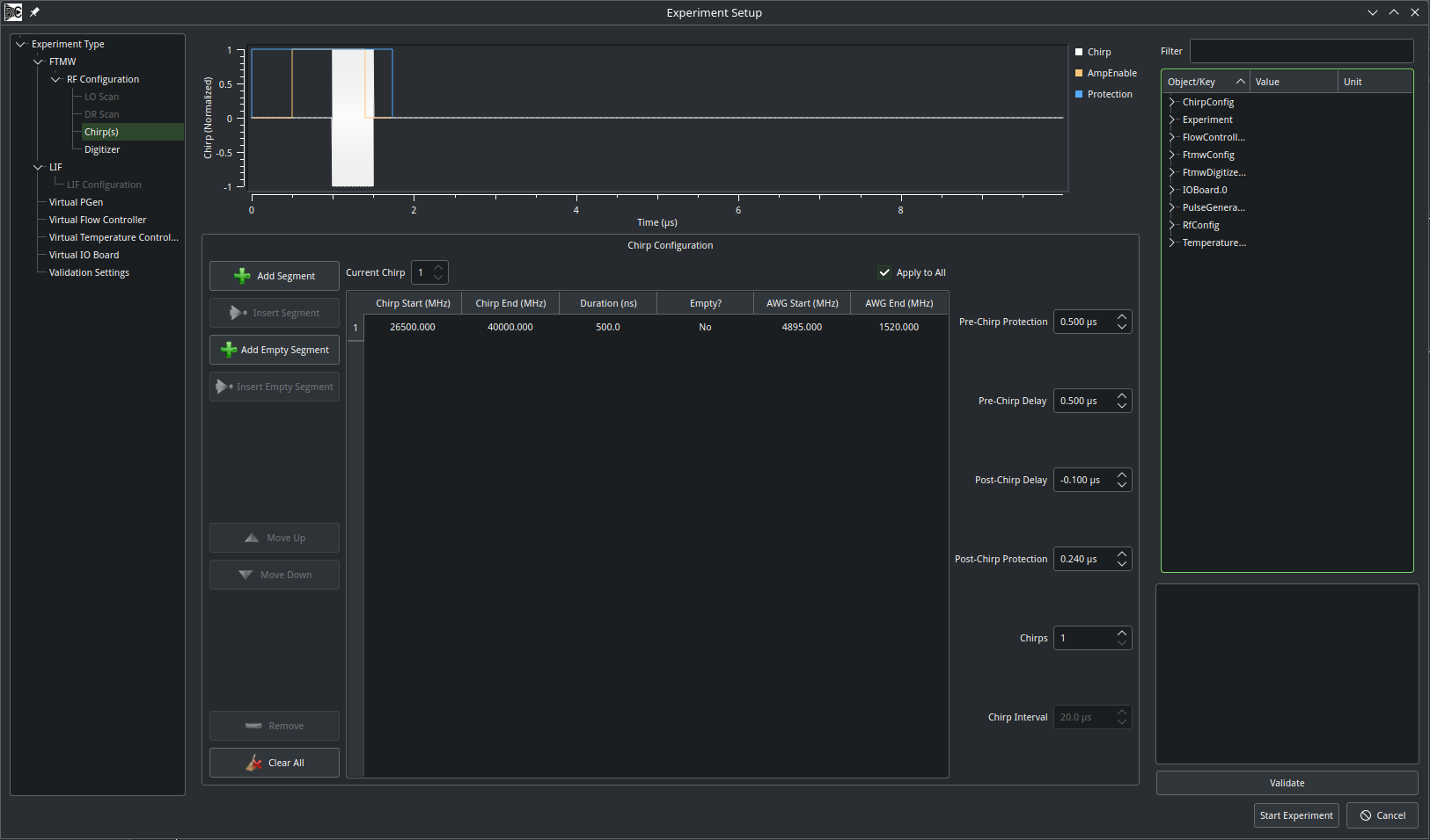
A chirp may consist of one or more segments that fall within the range of frequencies that may be generated by the AWG. A segment may also be empty, which would leave a gap in the waveform. When the “Add Segment” button is pressed, a new segment is appended to the end of the table; “Insert Segment” is available when a row of the table is selected, and the new segment will be inserted before the selected row. The “Add Empty Segment” and “Insert Empty Segment” buttons work similarly for blank segments. Individual rows may be moved up, moved down, or deleted with the corresponding buttons on the left.
In the table, the “Chirp Start” and “Chirp End” columns are derived from the the values configured on the RF Configuation page to convert raw AWG frequencies. Updating the Chirp Start value will also update the corresponding AWG Start frequency, and vice-versa. Chirps may go in either direction; the start frequency need not be less than the end frequency. The duration of the segment is entered in units of ns. A segment may be toggled between empty or non-empty. However, when converting an existing segment to empty, the start and end frequencies will be lost. When an empty segment is changed to non-empty, the AWG Start and End values are set to the device’s min and max frequencies, respectively.
In addition, for AWGs that support marker outputs, two output channels may be configured to control a protection switch (“Protection”) and an amplifier gate (“AmpEnable”/Chirp Delay). The protection signal activates at t=0, and then the amplifier gate activates after a delay indicated by the “Pre-Chirp Protection” box. Segment 1 of the AWG waveform then begins after the “Pre-Chirp Delay.” The “Post-Chirp Delay” and “Post-Chirp Protection” boxes are both referenced to the end of the chirp.
Note
Soon, Blackchirp will add support for an arbitrary number of markers, and all will be referenced to the start and end of the chirp.
Finally, a single AWG record may consist of multiple individual chirps (each of which may be identical or different) separated by a user-defined interval. This is often used in conjunction with FastFrame/segmented memory acquisitions. The total duration of such a waveform is limited by the onboard memory of the AWG. This configuration is somewhat wasteful, as most of the data are simply blank. Blackchirp does not currently support configuring “Sequence Mode” on AWGs that would eliminate much of the dead space. If multiple chirps are enabled, then each individual chirp in the series can be configured by varting the “Current Chirp” box and un-selecting the “Apply to All” checkbox. In this manner one could, for example, generate a series of chirps of different durations to vary the alpha value, or construct a series of Strong-Field Coherence Breaking experiments at once.