Hardware Menu
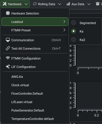
The Hardware toolbar menu, showing the entry order and the per-device actions contributed by the active loadout.
The Hardware toolbar button opens a menu with every instrument-level control and configuration surface, in this order:
Hardware Selection — opens the Hardware Configuration dialog.
Loadout submenu — lists all defined loadouts; the active one is checked. Switching is gated to the Disconnected and Idle states.
FTMW Preset submenu — lists the named FTMW presets belonging to the active loadout; the active preset is checked. Disabled when the active loadout has no named presets. Switching is gated to the Disconnected and Idle states.
Communication (
Ctrl+H) — opens the Communication Settings dialog.Test All Connections (
Ctrl+T) — attempts to reconnect to all hardware using the current protocol settings.FTMW Configuration — opens the FTMW configuration dialog for the active preset (see FTMW Configuration and FTMW Presets).
LIF Configuration (visible only when the LIF module is enabled) — opens the LIF configuration dialog.
Per-device entries — one entry per device in the active hardware map, labeled by the device’s hardware key (
Type.Label). Selecting an entry opens the Hardware Dialog for that device.
Communication
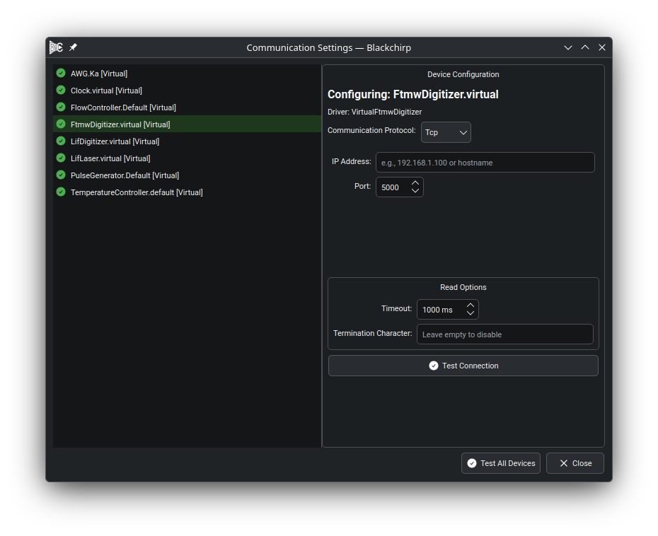
The Communication Settings dialog. The left panel lists every device in the active hardware map with a connection-status indicator; the right panel shows protocol-specific parameters for the selected device.
Each device exposes the communication protocols its driver supports:
RS232 — direct serial port connection (USB-to-serial adapters are common; FTDI-based adapters are recommended for their per-device serial numbers).
TCP — Ethernet connection via IP address and port number.
GPIB — IEEE-488 bus access, typically through a GPIB-LAN or GPIB-RS232 bridge (a Prologix GPIB-LAN controller is the supported driver).
Custom — driver-defined connection type used by some specialized hardware.
Virtual — software-only driver; no physical connection is required.
Selecting a protocol from the drop-down shows the protocol-specific parameter fields (port, baud rate, IP address, etc.) in the right panel. Common read options — response timeout and termination character — appear below the protocol fields and apply regardless of protocol type.
Click Test Connection to verify the selected device, or Test All Devices to test every device in sequence. Connection status is indicated next to each device name in the left panel.
Tip
For TCP instruments, use a dedicated network interface and configure devices on the link-local (169.254.x.x) address space. Many instruments support 1 Gbps; ensure the adapter and any switches match.
For GPIB devices, verify the connection to the GPIB bridge controller first; all GPIB instruments share that link.
If a device fails to respond after a protocol change, test the connection a second time. A device that received malformed bytes may need to drain its input buffer before it can process a valid query.
RS232 / USB-to-serial adapters on Linux
Note
This section applies to Linux systems only.
On Linux, USB-to-serial adapters appear as /dev/ttyUSBx device nodes,
where x is assigned in the order the devices are enumerated by the kernel.
That order is not guaranteed across reboots, so the device number for a given
adapter may change.
To assign a stable, adapter-specific symlink, configure udev rules using
the adapter’s serial number:
Find the serial number of the adapter assigned to
/dev/ttyUSB1:udevadm info --name=/dev/ttyUSB1 | grep serialNo
Edit the example rules file (
52-serial.rules) supplied with Blackchirp and add an entry for each adapter, referencing its serial number and the desired symlink name.Place the file in your distribution’s
udevrules directory (for example,/etc/udev/rules.d/on openSUSE).As root, reload and trigger
udev:udevadm control --reload udevadm trigger
After completing these steps, new symlinks are available and can be entered as
the RS232 device path in the Communication dialog. FTDI-based adapters are
recommended because they store a unique serial number in firmware, making them
reliable targets for udev rules.
Per-Device Entries
One menu action appears for each device in the active hardware map. Per-device entries remain reachable while a device is offline (including the Disconnected state that follows a critical hardware failure), so cached settings can be inspected, a bad communication parameter fixed, or a Python script reloaded without restarting the application. The Control tab of the Hardware Dialog is disabled while the device is offline and re-enabled when the device reconnects; the Settings tab and Python script-reload controls remain active throughout. See Hardware Dialog.