RF Configuration
The RF Config tab of the FTMW Configuration dialog configures the frequency conversion chain between the AWG output and the sample, and between the sample emission and the digitizer input.
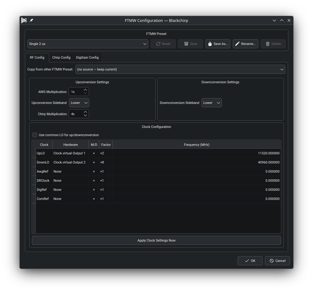
The RF Config tab. The clock role table assigns hardware clocks to each role; the multiplication factors and sideband selectors below the table describe the rest of the signal chain.
The diagram below summarizes Blackchirp’s model of the RF chain. The AWG output is multiplied, mixed against the upconversion local oscillator, and delivered to the sample. The sample emission is mixed against the downconversion local oscillator and digitized. Each labeled stage in the diagram corresponds to a setting on this tab.

Blackchirp’s signal-chain model. The AWG, upconversion LO, and downconversion LO are configured as clock roles; the multiplication factors and sideband selectors describe the external mixing stages.
Clock Role Table
The clock role table lists every clock role relevant to the active experiment type and lets you assign a hardware clock device to each role. Each row specifies:
Role — the function the clock serves in the signal chain (e.g., upconversion LO, downconversion LO, reference, DR clock).
Hardware — the clock device (profile label) assigned to that role. Only clock devices active in the current loadout are offered.
Frequency (MHz) — the operating frequency for that clock in the experiment.
Factor — a multiplication factor applied between the clock output and the actual signal frequency, to account for frequency doublers, triplers, or other multiplier stages in the external signal chain.
The Apply Clock Settings Now button sends the current clock configuration to the hardware immediately, without closing the dialog.
Common LO
When the Common LO checkbox is checked, Blackchirp uses the same hardware clock as both the upconversion and downconversion local oscillator. This is typical for homodyne spectrometers that share a single LO between the transmit and receive chains. When unchecked, independent hardware clocks can be assigned to the upconversion and downconversion roles.
For LO Scan experiments, at least one clock must be assigned to the upconversion LO role; if Common LO is off, a downconversion LO must also be assigned. A missing LO assignment in an LO Scan raises a validation error in the Experiment Setup dialog and prevents the experiment from starting.
For other experiment types, a missing LO is treated as a warning (the frequency is assumed to be 0 MHz) rather than an error.
Frequency Multiplication
Two multiplication factors govern the relationship between AWG output frequencies and the frequencies experienced by the sample:
- AWG Multiplication
Scales the raw AWG output frequency before upconversion mixing. A value of 2 indicates that the AWG output is sent through an external frequency doubler before reaching the mixer. The Chirp Start and Chirp End frequencies shown in the chirp segment table (see Chirp Setup) reflect the AWG frequency multiplied by this factor.
- Chirp Multiplication
Scales the upconverted chirp frequency to derive the frequency seen by the sample. For example, a value of 2 applied after an 18–26 GHz upconverted chirp results in a 36–52 GHz sample-frame frequency display. This factor affects how the chirp segment table converts between AWG frequencies and molecular frequencies.
Together these two factors let you configure Blackchirp to display and log frequencies in the reference frame of the sample, regardless of how many multiplication stages exist in the external signal chain.
Sideband Selection
Two sideband selectors — one for upconversion and one for downconversion — control which mixing product is treated as the signal frequency:
Upper — the sum frequency (LO + chirp) is treated as the signal.
Lower — the difference frequency (LO − chirp) is treated as the signal.
The sideband choices affect how Blackchirp converts between AWG frequencies and molecular frequencies in the chirp segment table and in sideband deconvolution.
Copy from Other FTMW Preset
A Copy from other FTMW Preset combo box at the top of each tab (RF Config, Chirp Config, and Digitizer Config) lists the other named presets in the active loadout. Selecting a preset seeds the current tab with that preset’s parameters as a starting point. The copy applies only to the tab it was triggered from and only to the in-memory widget state; nothing is committed until the dialog is accepted or the current preset is saved.