Digitizer Setup
The Digitizer Config tab of the FTMW Configuration dialog holds the settings sent to the FTMW digitizer at the start of a CP-FTMW acquisition.
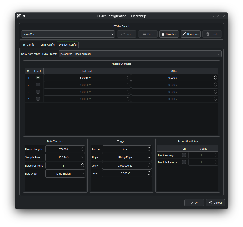
The Digitizer Config tab. The Analog Channels table occupies the top of the tab; the Data Transfer, Trigger, and Acquisition Setup groups sit side by side below it.
Analog Channels
Each analog channel on the digitizer occupies one row of the Analog Channels table. The Enable column selects which channel carries the FID signal; exactly one channel must be enabled, and the Experiment Setup validator reports an error if zero or more than one channel is checked. The Full Scale column sets the full vertical range from minimum to maximum (not the per-division scale), and the Offset column sets the vertical offset. For a DC-coupled input the signal range is offset ± full scale. The Full Scale and Offset cells are disabled on rows whose Enable checkbox is unchecked.
Note
In most CP-FTMW setups the digitizer should be AC-coupled, which makes the vertical offset effectively zero. Some digitizer drivers may not expose a coupling control through Blackchirp; in those cases the coupling must be set on the instrument directly.
Data Transfer
The Data Transfer group controls how the waveform is encoded during transfer from the digitizer to Blackchirp. Each row in the table holds one of:
- Record Length
Number of samples per FID. Dividing the record length by the sample rate gives the total time spanned by the FID, which determines the frequency resolution of the Fourier transform.
- Sample Rate
The digitizer’s sampling rate in samples per second. The available rates are populated from the per-device settings opened from the Hardware menu (see Hardware Dialog); the picker is a fixed list, not a free-text entry.
- Bytes Per Point
Number of bytes encoding each digitizer sample. Determined by the ADC bit depth (1 byte for 8-bit records, 2 bytes for 12- or 16-bit records) or by the accumulator width for on-board averaging. A digitizer driver may override this value automatically.
- Byte Order
Whether multi-byte samples are transmitted most-significant byte first (Big Endian) or least-significant byte first (Little Endian). A digitizer driver may override this value automatically.
Trigger
Blackchirp assumes the digitizer is triggered by an edge signal. The Trigger group has one row per setting:
- Source
Trigger input channel. On instruments that expose a dedicated auxiliary trigger input the value 0 displays as
Aux; positive integers index the analog channels.- Slope
Rising or falling edge.
- Delay
Time offset between the trigger event and the start of the acquired record, in microseconds.
- Level
Trigger threshold in volts. Range and step size follow the per-device settings.
Note
When a TTL-level marker output from an AWG is used to trigger a Tektronix oscilloscope, a trigger level of 0.35 V has been found to improve stability and phase coherence empirically. The origin of this improvement is not fully understood, but it is worth trying if coherence problems are observed.
Acquisition Setup
The Acquisition Setup group controls how the digitizer encodes one or more FIDs into a single transfer to Blackchirp. The table has two rows, Block Average and Multiple Records: the On column enables the row’s mode, and the Count column sets how many FIDs are combined into a single transfer.
- Block Average
Enable this row when the digitizer pre-averages multiple FIDs internally before transferring a single record to Blackchirp. For Tektronix oscilloscopes this typically corresponds to FastFrame acquisition with summary-frame transfer; for Agilent and similar instruments it corresponds to segmented-memory averaging. The Count value sets how many FIDs are averaged per transfer. When multiple chirps are configured, the count should match the number of chirps per AWG record.
When Block Average is active, the digitizer accumulates the configured number of shots before generating a transfer event. Blackchirp treats each transfer as one independent record and co-averages it with all previous records.
- Multiple Records
Enable this row when a single transfer consists of several independent FIDs concatenated end-to-end. The Count value sets how many FIDs are in each transfer; the total transfer length is Count × Record Length samples. This mode is commonly used with an AWG configured for a sequence of chirps, letting each digitizer record hold the response to one chirp. Individual records can be scrolled through in the CP-FTMW tab, and Blackchirp can co-average them in post-processing. When multiple chirps are configured, the count should match the number of chirps per AWG record.
On most digitizers the two modes are mutually exclusive — enabling one disables the other’s checkbox. Where the hardware supports both simultaneously, both rows can be on at once; ensure the device has sufficient onboard memory for the resulting data volume, since Blackchirp does not verify memory capacity at configuration time.
Maximizing Transfer Efficiency
Blackchirp treats each digitizer transfer as one independent record and co-averages it with the records collected so far. Polling a continuously-accumulating math waveform (as some oscilloscopes support) works only with a short accumulation window and incurs the associated overhead.
Two factors limit the acquisition rate:
Processing time on the digitizer. If the instrument spends time generating an internal average (e.g., a math waveform on a Tektronix scope), triggers are not accepted during that computation, which caps the effective FID rate regardless of transfer speed. FPGA-based instruments with hardware accumulators avoid this bottleneck entirely and can sustain much higher acquisition rates.
Transfer time over the connection. Blackchirp communicates with most digitizers over a 1 Gbps LAN interface. During a transfer, triggers arriving at the digitizer are ignored. For short records or moderate repetition rates this is rarely a bottleneck, but for very long records at high repetition rates increasing the number of averages per transfer reduces the fraction of time spent transferring and can significantly improve the overall FID rate.