Chirp Setup
The Chirp Config tab of the FTMW Configuration dialog defines the AWG waveform — one or more chirps with optional marker pulses. When an experiment starts, Blackchirp writes the configured waveform to the AWG. When no supported AWG is active, the chirp configuration is saved to disk alongside the rest of the experimental data but no waveform is generated.
The tab contains two sub-tabs: Chirp Segments and Markers. The Markers sub-tab is hidden when the active AWG reports zero marker channels.
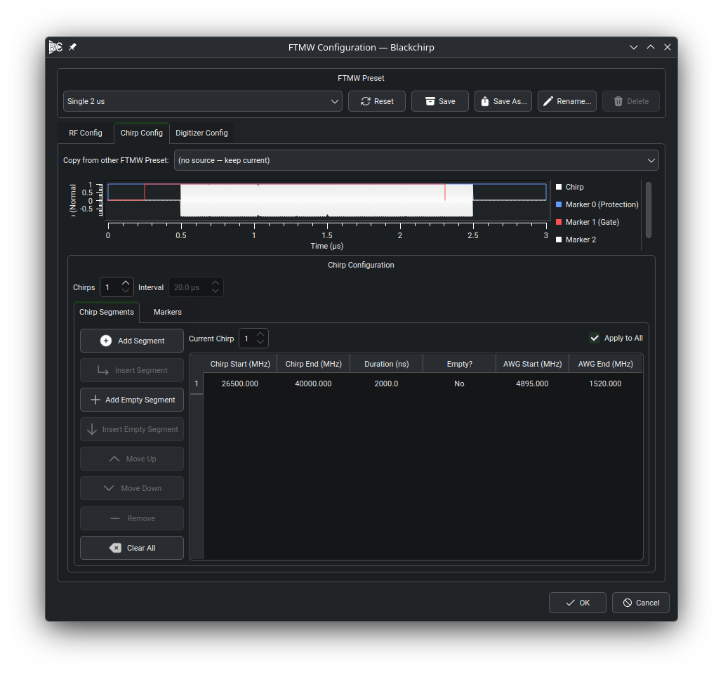
The Chirp Segments sub-tab. The table at the top lists each segment with its AWG frequency range, molecular frequency range, duration, and empty flag. The preview plot below the tab shows the resulting waveform as a frequency sweep over time, with one labeled rectangle per enabled marker channel.
Chirp Segments Tab
A chirp consists of one or more segments. Each segment sweeps continuously from a start frequency to an end frequency over a specified duration. A segment may also be empty, which inserts a gap of silence into the waveform at that position.
The toolbar buttons above the table manage segments:
Add Segment — appends a new non-empty segment at the end of the table.
Insert Segment — inserts a new segment before the selected row.
Add Empty Segment / Insert Empty Segment — work the same way but create empty (silent) segments.
Move Up / Move Down — reorder the selected segment.
Remove — deletes the selected segment or segments.
Clear — removes all segments.
In the segment table the Chirp Start and Chirp End columns display molecular frequencies derived from the AWG frequencies using the upconversion and multiplication settings configured on the RF Config tab (see RF Configuration). Editing either the AWG frequency or the corresponding molecular frequency column updates the other automatically. Chirps may go in either direction; the start frequency need not be less than the end frequency. Duration is entered in nanoseconds.
Converting a segment to empty discards its frequency values. Converting an empty segment back to non-empty sets the AWG Start and End frequencies to the device’s reported minimum and maximum, respectively.
Multiple Chirps
A single AWG record may consist of multiple chirps separated by a user-defined inter-chirp interval. This is often used in conjunction with FastFrame or segmented-memory acquisitions, where each digitizer record contains one FID per chirp. The total waveform duration is limited by the AWG’s onboard memory.
To enable multiple chirps, increase the # Chirps spinbox. The Interval spinbox sets the time between successive chirp starts in microseconds and is enabled only when the chirp count is greater than one.
By default, all chirps share identical segment tables (Apply to All checked). To configure individual chirps, uncheck Apply to All and use the Current Chirp spinbox to select which chirp to edit. This lets you create, for example, a series of chirps with varying durations (to sweep the alpha parameter) or a Strong-Field Coherence Breaking sequence within a single AWG waveform.
Note
When multiple chirps are configured, Blackchirp checks that the digitizer acquisition mode matches. If the digitizer does not support multi-record mode, or if the number of chirps does not match the configured number of block averages or digitizer records, a validation warning is shown in the Experiment Setup dialog. See Validation Settings for details.
Markers Tab
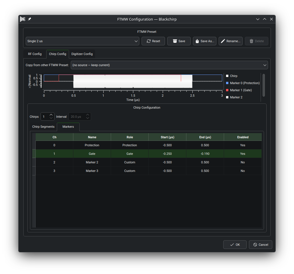
The Markers sub-tab. Each row in the table corresponds to one physical marker output on the AWG; the preview plot below shows the marker pulses overlaid on the chirp waveform.
The Markers sub-tab is visible only when the active AWG reports at
least one marker channel (markerCount >= 1). When the AWG has no
marker outputs the sub-tab is hidden and no marker configuration is
needed.
Each row in the marker table corresponds to one physical marker output on the AWG, indexed from 0. The columns are:
- Ch
Marker channel index (0-based). Channel 0 maps to physical output 1, channel 1 to physical output 2, and so on.
- Name
Editable label. When
markerCount >= 2the defaults areProtection(channel 0) andGate(channel 1); additional channels default toMarker N.- Role
Functional role for this channel — Protection, Gate, Trigger, or Custom. The role drives safety validation; see Protection Marker Validation.
- Start (μs)
Start time of the marker pulse relative to the chirp start. A negative value means the pulse begins before the chirp.
- End (μs)
End time of the marker pulse relative to the chirp end. A positive value means the pulse extends past the end of the chirp.
- Enabled
Checkbox. Disabled channels generate no output; their timing settings are preserved but ignored.
Default Start and End values when markerCount >= 2 are −0.5 μs and
+0.5 μs on both the Protection and Gate channels, giving 0.5 μs pre-
and post-chirp margins.
Note
Start and End times are defined relative to each chirp’s start and end within a multi-chirp waveform. Absolute timing (firing once over the whole waveform rather than once per chirp interval) and per-chirp marker overrides are not exposed in the user interface.
Protection Marker Validation
When the active AWG has at least one marker channel, Blackchirp validates the Protection marker configuration every time you advance through the Experiment Setup dialog. The validation compares the enabled Protection and Gate marker timings against the chirp and emits warnings for the following conditions:
“No protection marker is configured.” — No channel has the Protection role. Add a channel with role Protection to silence this warning.
“Protection marker is disabled while the chirp is active.” — A Protection-role channel exists but its Enabled checkbox is unchecked. Either enable the channel or remove it.
“Protection pulse starts at or after the chirp.” — The Protection channel’s Start (μs) value is ≥ 0. The protection switch must open before the chirp begins; set Start to a negative value.
“Protection pulse ends at or before the chirp.” — The Protection channel’s End (μs) value is ≤ 0. The protection switch must remain open past the end of the chirp; set End to a positive value.
“Protection pulse starts after the amp enable pulse.” — A Gate channel is enabled and the Protection channel’s Start time is later than the Gate channel’s Start time. The protection switch must open before the amplifier gate.
“Protection pulse ends before the amp enable pulse.” — A Gate channel is enabled and the Protection channel’s End time is earlier than the Gate channel’s End time. The protection switch must close after the amplifier gate.
These are warnings, not errors. The experiment can still start if they are present, but incorrect protection timing can damage sensitive amplifier components. Review the warnings carefully before proceeding.